May 1st 2009
Kit 5 has arrived rather later than I had hoped but; I've been away for a week, Andy has been to the Large Scale Model Rail Exhibition, Easter has got in the way and after all that it is obvious that a lot of work has gone into the parts in this kit as it is actually 4 kits in one:
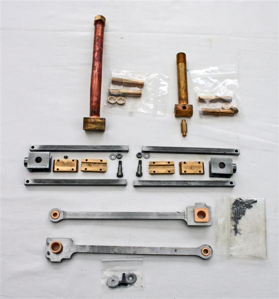
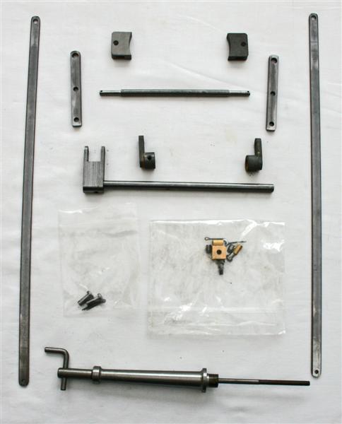
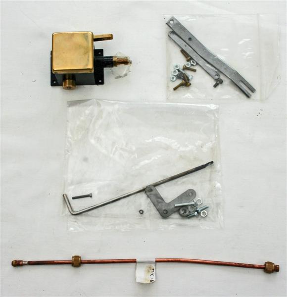
| Kit A: connecting rods, cross- heads, sliders and rails, blast pipe and steam tee. Note: The blast pipe will be made in 2 parts in future to avoid the problems I had in kit 8 | Kit B: brake rods, hangers, shoes, brake stand and the various linkages Click here to go to my write up of kits B,C and D | Kit C: lubricator, linkage and pipework Kit D: draincock operating levers (in the bag in the centre of the image) |
Kit A Assembly starts with fitting the connecting rods by turning the wheels to position the crank pins at the furthest backward point, sliding the rod bearing onto the crankpin then springing the rod behind the motion plate and up into position. Sounds a bit brutal but it works OK.
Next are the crossheads. Unfortunately this is where things started to go a bit pear-shaped. It was late afternoon and I thought I'd grab an hour before dinner to make a start on these. The instructions say you can assemble the sliders onto the crossheads before fitting the whole assembly onto the piston rod, or you can do the assembly afterwards. Unfortunately the first crosshead I picked up didn't have any screw threads in the holes on one side for the slider fixing bolts. I put that away for referral to Andy and picked up the other one. Unfortunately, again, I didn't read on far enough where it says to make sure the sliders go around the guide bars before mounting them. That warning really needs to go at the beginning of the paragraph. Needless to say they didn't fit so they had to come off again.
The instructions don't say what to do if the sliders and guides don't fit, but fine wet&dry used on a flat surface to polish up the sides of the guide bars, together with careful use of a swiss file on the brass sliders to remove some small burrs, did the trick and the sliders move nicely up and down the guide bars.
Then things went decidedly down hill. A bolt goes vertically through one end of the guide bar and into a threaded hole in the cylinder back plate. After fiddling around under the steam chest packing nut for several minutes trying to start the bolt, I took off the steam chest for a closer look - no thread in the hole! At which point I said "Oh bother!" and went indoors for my dinner!
A call to Andy has a replacement back plate and crosshead being sent same day (to be exchanged for the incomplete ones) It's a shame I've got to disassemble the cylinder on one side to get the backplate off and then refit everything, but I guess these things just happen in a very busy workshop. I really must get into the habit of examining all the parts when they arrive to save the frustrations that otherwise occur.
Anyway, next day, replacement parts arrive as promised and I soon have the new back plate in place. I decided to go ahead and fit the crosshead and bars while I have the steam chest off as this will give me better access. It's a bit of a fiddle to get the bolt, that joins the cross head to the connecting rod, in place as it's fitted from the inside face of the crosshead. But it goes in fairly easily and I then bolt up the guide rails as instructed.
The instructions do say that everything will be very tight and I should just be able to turn the wheels. With only one crosshead fitted it proves impossible to turn the wheels past the point where the piston is at its furthest rearward travel - everything just locks up solid. Further investigation suggests the crosshead is jamming on the bottom guide rail at its most rearward point. A little file work on the rear fixing bolt hole in the motion plate, as suggested in the instructions, drops the rail a fraction and makes some improvement but it still tends to jam. I'll have to investigate further when I get back from a trip next week.
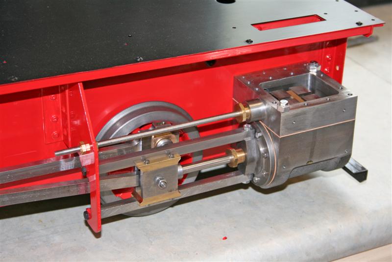
After refitting the steam chest, this is a picture of the right hand side assembly completed. The two large nuts under the steam chest bolts are just temporary and will allow me to turn the whole chassis upside down to fit the draincocks later on without risk of damage to the valve rods.
Then it was time to start on the left hand side. The process I used here, based on my experiences with the right side, was as follows:
1. Check that the cylinder back plate is centralised as above. I left the bolts slightly loose until later
2. Polish the guide bars with fine wet&dry, and check the brass sliders for burrs with a swiss file, until they move easily along the bars. Fit the sliders to the crosshead.
3. Fit the bottom guide bar, sit the crosshead on it and then fit the top bar. Check that the crosshead moves freely along the bars. I found I needed a shim under one end of a bar where it bolts to the cylinder cover, and a slight opening up of one of the bolt holes on the motion plate. We are talking very small amounts here, just manufacturing tolerances I suspect.
4. Check that the bolt that fixes the connecting rod to the crosshead will go through the rod bearing. Mine wouldn't until a bit of work with wet&dry on the bolt shank. Partially fit the bolt and check that the crosshead will still move along the bars with the connecting rod attached. I needed to open out one of the guide bolt holes in the motion plate a fraction more as the crosshead tended to jam at its rearmost point. Tighten the bolts in the rear cylinder cover
5. Disconnect the connecting rod from the crosshead and remove the top and bottom guide bars. Fit the crosshead to the piston rod, refit the guide bars, move the cross head right back and tighten the rear fixing bolts, do the same for the front bolts. Fix the connecting rod to the crosshead and with a bit of luck you'll find that everything will turn over nicely.
Although I need to grip two wheels with my office worker hands, I can now turn the whole lot over. It's still stiff but there don't seem to any more of the tight spots that were there before.
According to the manual, the next job in kit A is to fit the steam and exhaust pipes but as these will stop me from turning the engine upside down, and because the steam chests are not yet properly secured, I'm going to leave them until later and move on to Kit 5B.
As building this part of the kit has developed into a bit of a saga and extends to several screens, I'm going to start a new page for kits 5B,C and D here
Back to kit 4 Home On to kit 5B,C,D