It's been a while since my last update due to time spent repainting the front wheels and reassembling everything to get back to where I was before the problem with the crankpins and crossheads. While I was waiting for paint to dry, I got on with some other parts of the kit as far as I could.
Kit 5B The Brakes
Assembly is fairly straightforward, although the brake shoe castings seem to have been made to a different radius to the wheels resulting in just the tips of the shoes touching the wheels. Some work with a file makes them a better fit - doubtless they will wear-in in time. The shoes are fitted to the hangers with a pin held in place with a split pin fitted from the rear before mounting the hangers on the supports on the chassis frame. The nuts for this were missing but I found a couple in my bits box.
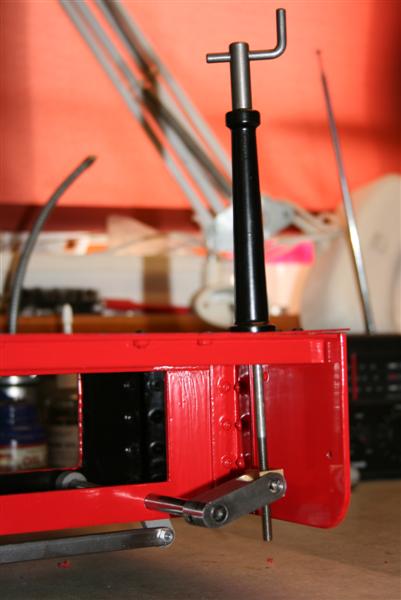
The brake rods were then fitted into the appropriate holes in the frames with the operating fork on the left (not on the right as shown in the picture in the instructions!) Up to this point, there has been no instruction to fit the footplate. However, it soon becomes apparent that now is the time to do that in order that we can fit the brake stand. I subsequently had to remove the brake stand again so that I could turn the engine upside down to get at the drain cocks. I would therefore recommend that you leave the brake stand off until you are sure you have finished with the need to turn the engine over.
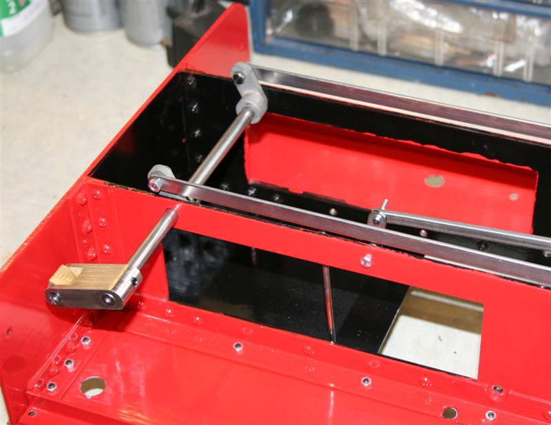
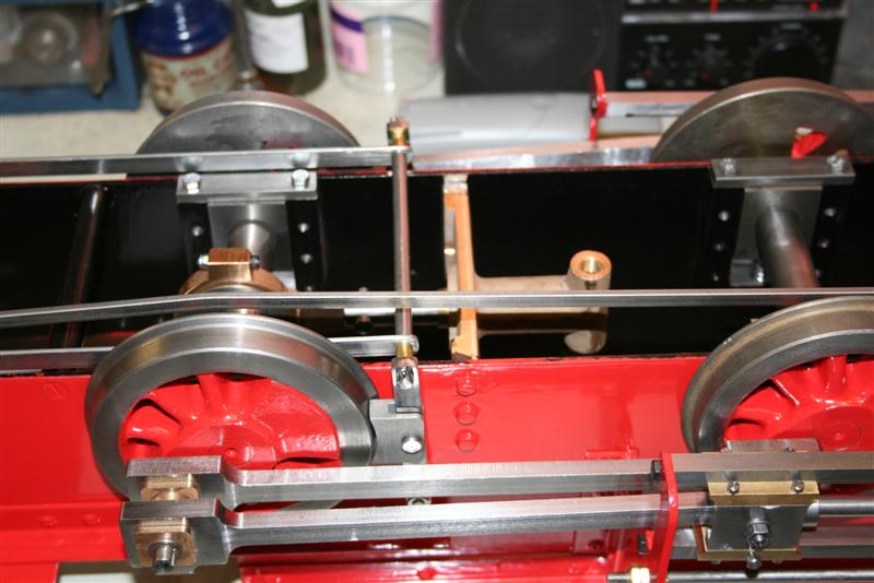
The first two pictures (click to see full size) show the brake shoes, hangers and brake rods, the last one showing the brake stand fitted to the footplate. The cranked rod that you can also see is the draincock operating lever and you can also see the draincock operating lever going through the cab floor (see Kit 5D below).
Kit 5C The Oil Pump
Next, bolt the link between the fork and the pump lever using the two special bolts supplied.
The last job is to bend the copper pipe between the pump and the oil check valve on the steam tee. I wasn't looking forward to this as I was convinced I would kink the tubing. However, with the steam tee temporarily in place, I carefully bent the tubing bit by bit and was pleasantly surprised how straightforward it was. The copper is very soft and bent easily under my thumbs. It's a bit tortuous passing the pipe through the side frame and down to the check valve but it looks OK to me. I can't fix it permanently until the steam tee is fitted.
Kit 5D The Draincocks
The draincocks and most of the linkage was supplied with Kit 4 but I elected not to fit them at that point as I felt they would be rather vulnerable, being low to the bench top while I was working on other parts. Now was the time to fit them however. First challenge is to fit them so that they are reasonably tight and all facing the same way. They are marked Left and Right so that bit is easy. Wrapping PTFE tape around the threads is very fiddly as they are so small. Varying the amount of tape and by trial and error, I eventually managed to get them all in place with the levers all on the inside and in line.
Next was to fit the link between each pair. First, fit the headless bolts in the centre of the links that will go into the fork of the actuating lever. Next pass a bolt through the draincock lever into the threaded holes in the end of the link. Here's where I struck a snag as the bolts supplied would not go through the draincock levers nor into the threaded holes at the ends of the link. It turned out, after talking to Andy, that the threaded holes had been cut too small. A replacement set was sent and on we went. I had to open out the holes in the draincock levers however, as the bolts would not go through them.
Then bolt the draincock shaft in place across the frames with the actuating lever on the left and the pins on the links located into the forks on the shaft.
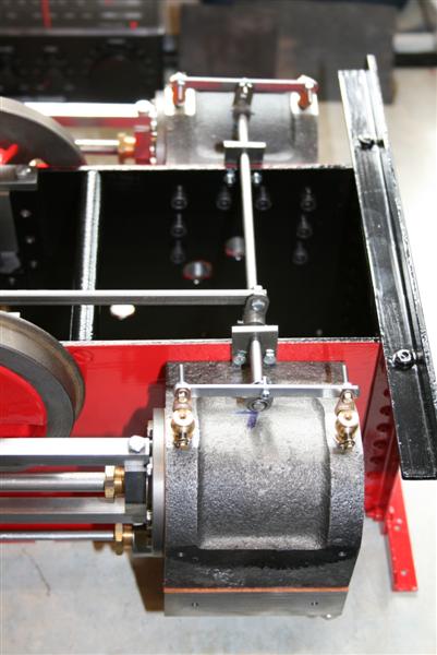
Now we move onto the parts supplied with kit 5D which is the actuating lever for the cab floor and the rod to join it to the draincock shaft. I found this part a bit tricky as my copy of the instructions had very poor photos and it was not at all clear which bolts went where. After a bit of trial and error I got it all together and the lever in the cab floor moves the draincocks quite easily.
Several of the bolts have no way of locking them to allow movement of the parts in operation without it all falling apart again. Obviously, you are expected to secure all this with Loctite although that isn't mentioned anywhere. Up to this point, I had deliberately not done that as I wanted to be sure I'd got everything fitted correctly first. So now it was a matter of going back over all the nuts and bolts and securing them with Loctite, at the same time cutting off the surplus bolt length at the draincock levers.
So there we are, all parts except the steam and exhaust tees have been fitted and the Kit 5 box is finally empty. I'm looking forward to Kit 6 which has the valve gear and smokebox and saddle I understand. Hopefully that will be here in the next week or so and we can finally try to run it on compressed air. I still have a nagging doubt over a slight tight spot when turning it by hand but we shall see!
Until the next time...
Having
decided which set of screws was which, as they didn't tie in with
the instructions, the pump simply bolts to the left hand running board.
I've left the piece of tape over the outlet in place for now as
there's a small spring and ball in there which I'll probably lose
otherwise. 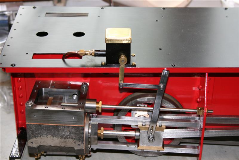
Next, bolt the link between the fork and the pump lever using the two special bolts supplied.
The last job is to bend the copper pipe between the pump and the oil check valve on the steam tee. I wasn't looking forward to this as I was convinced I would kink the tubing. However, with the steam tee temporarily in place, I carefully bent the tubing bit by bit and was pleasantly surprised how straightforward it was. The copper is very soft and bent easily under my thumbs. It's a bit tortuous passing the pipe through the side frame and down to the check valve but it looks OK to me. I can't fix it permanently until the steam tee is fitted.
Kit 5D The Draincocks
The draincocks and most of the linkage was supplied with Kit 4 but I elected not to fit them at that point as I felt they would be rather vulnerable, being low to the bench top while I was working on other parts. Now was the time to fit them however. First challenge is to fit them so that they are reasonably tight and all facing the same way. They are marked Left and Right so that bit is easy. Wrapping PTFE tape around the threads is very fiddly as they are so small. Varying the amount of tape and by trial and error, I eventually managed to get them all in place with the levers all on the inside and in line.
Next was to fit the link between each pair. First, fit the headless bolts in the centre of the links that will go into the fork of the actuating lever. Next pass a bolt through the draincock lever into the threaded holes in the end of the link. Here's where I struck a snag as the bolts supplied would not go through the draincock levers nor into the threaded holes at the ends of the link. It turned out, after talking to Andy, that the threaded holes had been cut too small. A replacement set was sent and on we went. I had to open out the holes in the draincock levers however, as the bolts would not go through them.
Then bolt the draincock shaft in place across the frames with the actuating lever on the left and the pins on the links located into the forks on the shaft.
Now we move onto the parts supplied with kit 5D which is the actuating lever for the cab floor and the rod to join it to the draincock shaft. I found this part a bit tricky as my copy of the instructions had very poor photos and it was not at all clear which bolts went where. After a bit of trial and error I got it all together and the lever in the cab floor moves the draincocks quite easily.
Several of the bolts have no way of locking them to allow movement of the parts in operation without it all falling apart again. Obviously, you are expected to secure all this with Loctite although that isn't mentioned anywhere. Up to this point, I had deliberately not done that as I wanted to be sure I'd got everything fitted correctly first. So now it was a matter of going back over all the nuts and bolts and securing them with Loctite, at the same time cutting off the surplus bolt length at the draincock levers.
So there we are, all parts except the steam and exhaust tees have been fitted and the Kit 5 box is finally empty. I'm looking forward to Kit 6 which has the valve gear and smokebox and saddle I understand. Hopefully that will be here in the next week or so and we can finally try to run it on compressed air. I still have a nagging doubt over a slight tight spot when turning it by hand but we shall see!
Until the next time...