Back to kit 3
Home
On to kit 5
Kit 4: Cylinders and Steam Chests
(click on any image to enlarge)
March 9th 2009
Kit
4 has arrived and contains the "business end" of the loco. I've been
looking forward to this part of the building process as to me it
represents what a steam loco is all about. I've always had a
general idea as to how they work, but by putting this little lot
together I'll definitely know what it's all about!
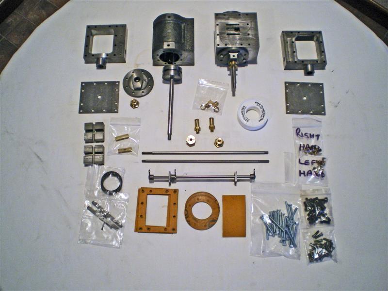
So this is what will keep me occupied next :-
Cylinders, front
and rear covers, steam chests, pistons, gaskets, snifter valves, slide
valves and rods, drain cocks and operating linkageRemember
that I'm no engineer, but I have to say I'm very impressed with the
quality of the workmanship on these parts. The fit and finish
seems to be absolutely first class with little if any fettling required
as far as I can see at this stage. I think I'm going to enjoy this
part of the build.I've
read through the instructions a couple of times to make sure I have a
general idea of what goes where and the first job is to grind in the
slide valves to the cylinder tops (lapping?). This is in order to
get a good steam tight seal around the valve. Surprisingly, there
is no grinding paste included in the kit. I find that a bit odd
since there is a reel of PTFE thread sealing tape in this kit and there
have been other consumables like the loctite glues included in the
other kits. A trip to Halfords reveals that I have to buy a car
valve grinding kit complete with coarse and fine grits and a piece of wood with
two suckers on it. Total cost of £3.99 to just use about 50p
worth of fine paste. Shame really when it could probably have been
included in the kit for next to nothing. Something to think about for
the future perhaps?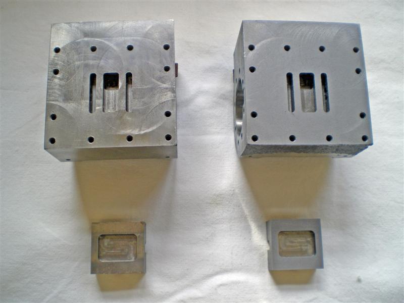
So after about an hour, or so, I've finished lapping the slide valves to
the top face of the cylinders. Here's a picture before and after.Copious
amounts of paraffin are used to wash away all traces of the grit using
a brush and an old baking dish (well it's old now!) Next
job is to fit the cylinders to the chassis frames. However, there
is so much paint in the bolt holes that the bolts won't go anywhere
near them. They're a deliberately tight fit so that the cylinders
will line up properly. I used a 4.5mm drill in a hand brace
to carefully remove the paint without taking any of the metal.
The bolts are still a tight fit but with care they will go
through the holes. I also used a 3mm drill to clear the holes
that will take the draincock operating brackets.While
supporting the weight of the cylinder with one hand, I screwed in
one allen bolt to each corner using fingers only at this stage.
Then screwed in the remainder hand tight before reaching for the
allen key. There's no particular pattern specified but I did the
four corners diagonally and then moved alternately from sides
to the bottom, tightening bit by bit. I was trying to ensure
that all the bolts went in at the same torque - a bit like we used to
do when refitting the cylinder head of a car engine. Not sure it
was necessary but can't do any harm.Next
is to fit the rear cylinder cover. You'll need a 6BA tube/box
spanner for this, it's the only way of reaching the two bolts on the
inner edge of the cover, and it's quicker than using an open ended
spanner. I spun the bolts in finger tight with the tube spanner
and then carefully tightened them using the tommy bar, again working
diagonally across the cover to keep things nice and even. I
didn't make them too tight, if there's any leaks come steam
up time, I can always tighten them a little further, but I don't fancy
a broken bolt at this stage!Now
fit the neoprene(?) piston ring to the piston, oil the piston and
cylinder, line up from the front of the cylinder and push
into place. It goes in quite easily but once in I can't move it with
the piston rod. Front cylinder cover is left off at this
stage until we get the cross head and connecting rod when I will be
able to check all's well.
The piston stuffing nut can be screwed in about halfway at this stage. 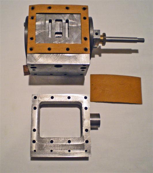 Steam
chest and gasket next. The
instructions refer to two small gaskets
to pack out the gap on the cylinder face between the gasket and the
side of the chassis frame. I can't find these but I do find what I
thought was a bit
of gash gasket material which I'd almost thrown away as it had picked
up a couple of deep dents in transit. I cut a 0.5 inch wide strip
from this spare piece to
fit. The instructions could be a bit clearer for us novices but it all
makes sense eventually. The picture shows this more clearly. The
steam chest is temporarily fitted with 4 bolts to hold it in place
until we get to do the valve timing and fit the cover permanently.Now
fit the valve rod guide to the motion plate after clearing paint again,
this time with an 8mm drill twisted in by hand. The guide goes in
from the front of the engine and with the oil hole uppermost
(naturally!) The valve nut (the oblong brass nut that goes into
the slot in the top of the slide valve) is next and needs a quick clean
up with fine emery so that it will fit the slot. The stuffing nut
then needs to be screwed partly into the steam chest except that it
won't start. The thread is a bit rough where it's been cut and I
needed to smooth this out by wrapping a piece of wet and dry round it
to smooth it off. We're leaving the graphite yarn packing out at this stage as it will apparently get in the way.
Steam
chest and gasket next. The
instructions refer to two small gaskets
to pack out the gap on the cylinder face between the gasket and the
side of the chassis frame. I can't find these but I do find what I
thought was a bit
of gash gasket material which I'd almost thrown away as it had picked
up a couple of deep dents in transit. I cut a 0.5 inch wide strip
from this spare piece to
fit. The instructions could be a bit clearer for us novices but it all
makes sense eventually. The picture shows this more clearly. The
steam chest is temporarily fitted with 4 bolts to hold it in place
until we get to do the valve timing and fit the cover permanently.Now
fit the valve rod guide to the motion plate after clearing paint again,
this time with an 8mm drill twisted in by hand. The guide goes in
from the front of the engine and with the oil hole uppermost
(naturally!) The valve nut (the oblong brass nut that goes into
the slot in the top of the slide valve) is next and needs a quick clean
up with fine emery so that it will fit the slot. The stuffing nut
then needs to be screwed partly into the steam chest except that it
won't start. The thread is a bit rough where it's been cut and I
needed to smooth this out by wrapping a piece of wet and dry round it
to smooth it off. We're leaving the graphite yarn packing out at this stage as it will apparently get in the way.
The
valve, with the valve nut in place, is then laid on the cylinder face
and the valve rod is slid through the valve rod guide, then through the
stuffing nut and into the steam chest to screw into the valve nut.
Needed to fiddle around a bit here as the valve nut is slightly
lower than the valve rod and also keeps moving from side to side.
I used a pair of long nosed pliers to carefully grip the
ends of the valve nut so that I could line it up with the start of the
thread on the valve rod. (Sorry about all the references to valve
this, and valve that, but I found it a bit difficult to follow which
bit was being talked about in the instructions at times. Perhaps
using the full description of each piece makes it a bit clearer)
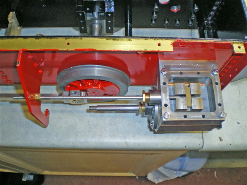
Here's a picture of the finished assembly on the right hand side of the engine. I then repeated the exercise for the left hand assembly.The
instructions now say to fit the draincocks and linkage and it seems to
me that the simplest way to do this is to turn the whole engine upside
down. However, I'm a bit concerned that this will place some
strain on the valve assemblies as the steam chests are only held in
place by 4 bolts which will not screw all the way in as the top cover
is not yet fitted. If the steam chests drop, I'm worried that all
that weight might bend the valve rods so I'm going to wait until I get
the next kit until I fit these. Based on past experience with my
Polly 2, the draincocks are pretty vulnerable under there anyway and
have a nasty habit of biting you if you put your hand anywhere near
them. Another good reason for leaving them off for now!One
thing I have realised is that, when comparing what we've done so far
with the picture of the prototype on Polly's website (shown on my home
page), the piping for the steam inlet and exhaust is completely
different. The picture shows it like the Sweet Pea with the pipes
coming out of the top of the steam chest, whereas now I've fitted this
lot together, I realise that all the pipe work is inside the frames as
on my Polly 2. I'm left wondering what the two oblong slots in
the footplate are for (see the picture on Kit 2
page), and also what the 4 little screw threaded holes are on the top
of the steam chest beside the chassis frame. You can see
these in the picture above - answers on a post card please... Andy
has said that they would be developing the design from the prototype as
they go along so I'm sure all will be revealed in due course.This beast is beginning to get a bit heavy
now - it weighs in at 17Kg, or about 37lbs already. Target weight is
around 50Kg if I remember correctly. Will have to find somewhere to
park my Polly 2 soon as I'm going to need my hydraulic lifting table
before long. So with the date at March 19th, that's about
as far as I can go for now. I'm
hoping that kit 5 will be along around the beginning of April
and will contain the remaining valve gear so that I might even be
able to do a test run on air. So come back soon and see.Footnote:
Geerlig has advised that the steam inlet and exhaust pipes that we can
see on top of the steam chests are in fact dummies and will be included
in the kits. The 4 small threaded holes are for the flanges of
these pipes. He has also advised that I won't be able to test run on air until I've completed kit 6. Also see new gallery page with pictures of Caroline both prototype and production versions which Geerlig has very kindly sent me to display.Back to kit 3
Home
On to kit 5