Kit 6 has arrived and contains all the bits to make up the reverser lever and stand, plus the weighshaft and associated linkage to control the slide valves fitted earlier. Hopefully, after I have completed all this, I should be able to test run the engine on air and find out if I have any hope of becoming a competent model engineer!
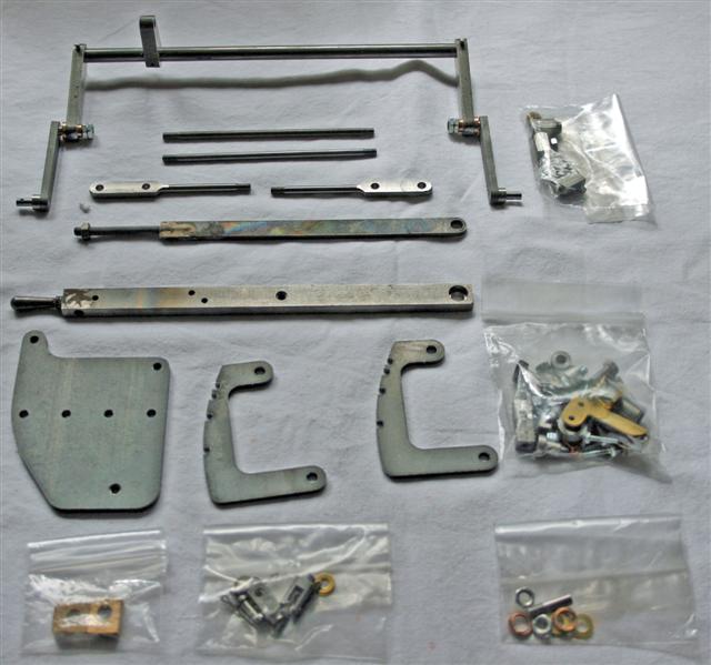
There seems to be an awful lot of small parts in little bags, and a quick read through the instructions reveals names of parts that I've never heard of. Worse still, it is not at all clear from some of the pictures, which part is being referred to in the text.
There is a photo, like the one to the left, with the names of the parts in box-outs, but it is so blurred that it is almost impossible to see the shape of the tiny parts. I feel a little daunted at the prospect of finding my way through this kit.
Assembly starts with the base of the reverser which is quite straightforward. Simply bolt it to the frame and then bolt the guide plates to that. Good clear photos with box-outs identifying the parts makes this a confident build.
The reversing lever is next assembled which required a fair amount of filing and polishing to make sure the locking lever engages and releases properly in the slots in the quadrant. Confusion here over what to use to secure the locking handle and the guide plate as there are 2 copper rivets supplied along with 2 bolts and nuts. The instruction says "push the supplied rivets or bolts through the holes" and the picture of the parts shows bolts and nuts for both!
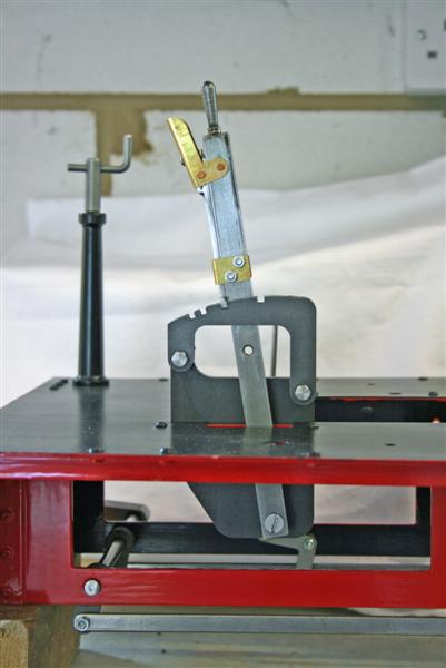
Luckily I have my Polly 2 which has a similar reversing lever, so I copy that and use the rivets to secure the handle, and the bolts to secure the guide. That proves to be a good choice as I have to remove the guide (the brass item half way down the lever) a couple of times as the locking lever jams when I tighten up the bolts.
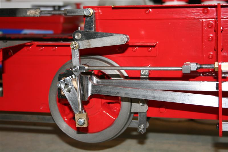
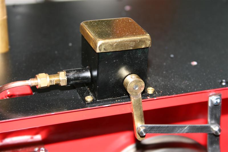
Incidentally, the reverser works in the opposite direction to what I'm used to on my Polly 2. It's lever full back to go forwards and full forward to go backwards!! That'll prove interesting when we start driving! Here's a picture of the finished assembly.
Next we start on the weighshaft and remaining parts. The weighshaft lever is already fitted to the shaft along with the reversing arms which is very helpful as it makes things clearer. First job, however, is to fit the weighshaft lever pin and loctite it in place. I got a bit confused here as it says "The weighshaft lever pin is now threaded and needs to be fitted with the thread to the right..." I thought it meant that the pin was to be threaded into the lever as the pictures showed a plain pin fitted with a hole for a split pin. However the hole in the lever wasn't threaded. I then realised it was saying that the pin is now threaded and not as in the pictures! Really must concentrate more!
The right hand reversing arm is to be fitted next but this has already been done for me, although the free reversing arm is just loosely fitted. I realise that I'm going to have to remove both the left hand arms in order to fit the weighshaft to the chassis and discovered that those parts are also just loosely assembled. I then needed to do some work on the free reversing arm pins on both sides so that they will fit properly into the bushes on the fixed arms, finishing up with tightening the nuts on the right hand arms. Hope that's all clear!
We then move on to combination levers and intermediate valve rods. Working my way through the parts, I remove sharp edges and trial fit the pieces together. I won't bore you with all the details but eventually I am happy that everything is ready to be threadlocked together ensuring that the parts end up square to each other.
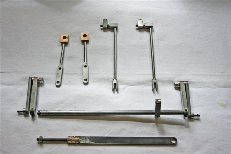
Here's a picture of the parts assembled. Combination levers are the two with the brass block bearings at top left, the intermediate valve rods top right, and of course the rest is the weighshaft. At the bottom of the picture is the reach rod to be fitted between the reversing lever and the weigh shaft.
(I actually only discovered my mistake with the lever pin after I had completed all the work above which is why the pin doesn't show in the photos)
The next job was to fit the weighshaft to the chassis. A trial fit showed that there was a fitting issue here as Andy had suggested to me in a recent phone call. There was a slight burr inside the weighshaft blocks fixed to the rear axle mounts. Much polishing of the weighshaft with fine emery, and careful file work on the blocks, and the shaft will now slide into position in the blocks. And here I thought I'd hit another snag as I couldn't find the two washers, one a large one with a grub screw, to locate the shaft in position. A call to Andy finds he is away on a well deserved break, so I'm stuck until he gets back. However, a week later I find a box containing the missing bits where I'd obviously put them for safe keeping and then forgotten all about them!
So having found the missing pieces that weren't, it didn't take long to assemble the remaining valve gear. Fit the weighshaft with its spacers and a locking grub screw on the left side, and then the left side reversing arms. Combination levers which join the reversing arms to the rear axle crankpins are fitted next. Finally the intermediate valve rods, which join the rod connected to the slide valves to the combination levers. The intermediate rods will have to be removed frequently during the valve timing set up so they are left without locking nuts and split pins for now. Last job is to fit the reach rod between the reverser on the footplate and the lever on the weighshaft, so that the reversing arm on the weighshaft is horizontal. Here are some pics of the finished assembly which probably explains things better.
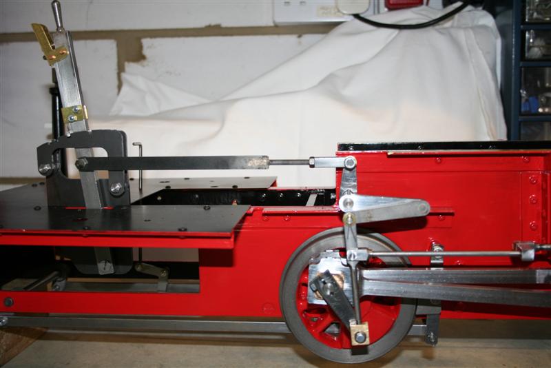
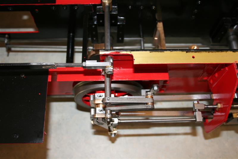
So then we come to the bit that I was not looking forward to - the valve timing. At this stage, the cylinder front end caps are still off as the instructions haven't mentioned fitting them and I thought it would help with the timing if I could see where the pistons were in their cycle. There are two whole pages of instruction on how to do the timing which I won't repeat here. The timing is adjusted by disconnecting the intermediate rods (the thin horizontal rod that you can see in the middle picture above) and twisting the main valve rod connected to the slide valve to lengthen or shorten it.
The first objective is to have the front inlet port just open when the piston is at its most forward position when in full forward gear. A balance needs to be struck with the opening of the front port in forward gear and the amount of opening of the rear port in reverse gear. The main difficulty I had was in getting both slide valves to open the relevant ports by the same amount, both in forward and reverse gear. After much twisting of the valve rods I got them as close as I could. The first paragraph of the instructions says "...there is no point in trying to get perfection, what we need is workmanlike performance". I suppose it must have taken well over an hour until I was satisfied I'd got it as right as I could - whether I have or not remains to be seen!
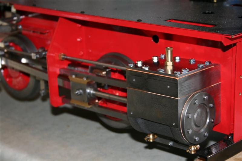
Finally, lots of twirling to fit the twelve 35mm long steam chest cover bolts and the eight front cylinder end cover bolts on each side and that just left the snifter valves. Here's a picture of the completed assembly.
So all that's left is to fit the steam and exhaust tees from kit 5, fix the running boards, join up the oil feed, borrow a compressor and then we should be able to run that elusive air test. Unfortunately it looks like that will have to wait until I get back from a combined holiday trip and visit to the Guildford Model Engineering Show where I have arranged to collect my boiler and smoke box and some other parts making up most if not all of kit 7.
August 4th
 So,
back from my trip, I fitted the steam and exhaust tees. Couple of
points here. First is to ensure that when you start screwing
the connectors into the steam chest and cylinders, you must make sure
that the tees are central between the chassis frames otherwise they
won't fit through the holes in the running board plate. This is because
while you are winding the connectors into the cylinders, you are unwinding them from the bottom of the tee at
the same time. If they are not central to start with you will not
be able to adjust them later. Second point is that to get to the
connectors for the exhaust tee, you will have to remove the front
buffer plate to be able to wield a spanner. Apart from that, no
real problems here.
So,
back from my trip, I fitted the steam and exhaust tees. Couple of
points here. First is to ensure that when you start screwing
the connectors into the steam chest and cylinders, you must make sure
that the tees are central between the chassis frames otherwise they
won't fit through the holes in the running board plate. This is because
while you are winding the connectors into the cylinders, you are unwinding them from the bottom of the tee at
the same time. If they are not central to start with you will not
be able to adjust them later. Second point is that to get to the
connectors for the exhaust tee, you will have to remove the front
buffer plate to be able to wield a spanner. Apart from that, no
real problems here.Having fitted the running board with just 4 bolts for now, I connected up the oil pump, poured in some oil, tried to bleed the air out but found I was getting no oil through the pump. After much trial and error, I gave up and called Andy for advice. Seems the pump, as supplied, is not set up and it's a job we have to do. After Andy explained the workings of the pump and the set up procedure, I set to and after about 20 minutes I had the problem solved.
In summary the set up process is as follows:
1. Check that the 3 grub screws on the lever, cam, and retainer are all in line (the one on my cam was loose).
2. Unscrew the pump assembly from the oil reservoir, be careful not to lose the spring and the two ball bearings, then screw it back in about one and a half turns and loosely tighten the lock nut.
3. Pour enough steam oil into the reservoir to cover the cam and pump assembly.
4. Turn the pump lever to the 9 o'clock position, place the palm of your hand over the reservoir and press down. Oil should come out of the end of the pump assembly. Watch out for the spring!!
5. Next is a process of trial and error: Screw the pump body further into the reservoir a half turn at a time. After each half turn, move the pump lever in the arc between 5 and 7 o'clock while holding the spring in position with your finger nail. Eventually oil will begin to come out of the pump body. The further you screw the pump body in,
the more oil will be pushed out at each stroke. Keep screwing in half turn at a time until the oil flow begins to lessen, then back off a half turn or two and tighten the lock nut.
 I
ended up with the distance between the lock nut and the end of the threaded pump
body at about 10mm. This can be adjusted to reduce the flow
in future, but I want plenty of oil during the running in phase.
I
ended up with the distance between the lock nut and the end of the threaded pump
body at about 10mm. This can be adjusted to reduce the flow
in future, but I want plenty of oil during the running in phase.Footnote: See First Steam November 9th. The 10mm noted above has turned out to be too short. I'm now nearer 13mm. The lever movement arc is also smaller at between 4 and 6 o'clock.
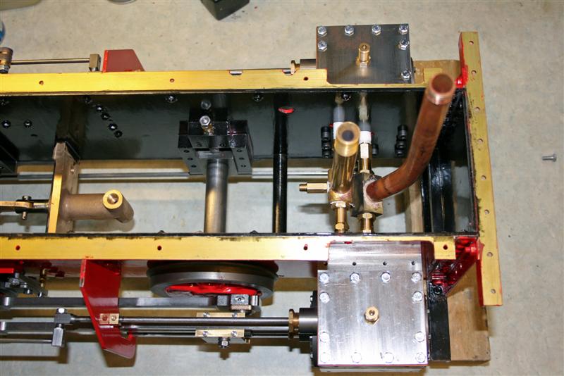
6. Connect up the linkage and the feed pipe and this is what it looks like.
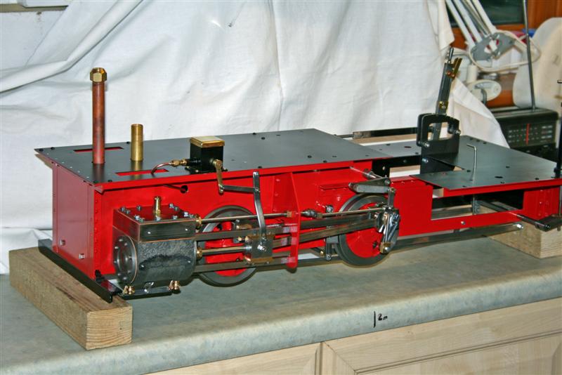
And here's a picture of everything assembled so far.
I've arranged to borrow a compressor early next week and can then finally see if my valve timing is any good!
Check back in a week's time!
August 10th
Finally I found time to take the engine to my expert friend, Paul, hooked it up to his compressor and it actually worked first time! To say I was surprised is an understatement - I had more or less convinced myself that I couldn't possibly have got the valve timing right. As it turned out I hadn't quite got it right as it wouldn't run when notched up. It would go full forwards and backwards though. We ran it for a while and then I carted the whole lot home to do some running in.
The next day I decided to remove the steam chest covers and check out the timing. A call to Paul explained in simple terms what I was supposed to be doing (sorry Geerlig, your way is too complicated for my simple brain). Essentially it's move the piston to front dead centre when the front port should just open, then move to rear dead centre and the rear port should open. Both ports should open by a similar amount during the whole cycle. A turn and a half of each valve rod soon achieved this. A check that the ports opened evenly when notched up (previously the rear ports hadn't opened at all in notch up), then a check on the reverse positioning and I was soon putting everything back together. Reconnecting to the compressor was amazing. Whereas it ran very clunkily before it was now much like a sewing machine and needed much less air - and it ran evenly when notched up too! Success and a workbench covered in oil - well I was told to make sure there was plenty!
So there we are at last - kit 6 is finished and I've started on the assembly for kits 7 & 8. See the following pages.