The instructions aren't quite ready yet, but I do have lots of photos showing where things go. Each pipe is numbered and I have a packing list with a description so I just need to sit down and study everything to decide what goes where. I will also need to clean up some of the excess solder on the tanks in the time remaining, a proper preparation for painting will have to wait until I get back.
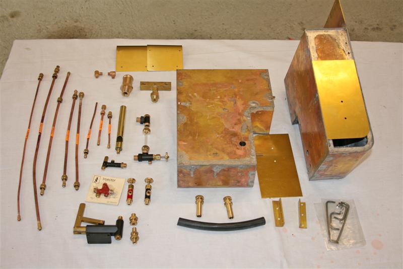
This kit contains the two side tanks and lids, hand pump, whistle and whistle valve, safety valve, injector, blower valve, pump bypass valve, turret and water gauge, all the pipe work and finally the cylinder covers.
September 6th
I decided to start with the fittings to the boiler. I had some photos from Geerlig, and of course my trusty Polly 2 to work from so I felt fairly confident. I found that I had to remove the firebox door to fit the clack valve on the lower right hand side of the boiler backhead. Not a big job but there's limited room to swing a spanner so it might be better to leave the door off until after the clack is fitted.
Not a lot else to report really, just a matter of fitting parts together with PTFE tape (why does that tape reel always drop onto the floor at the crucial moment?)
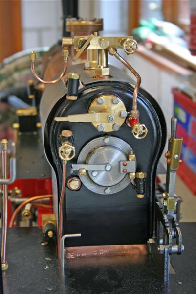
I decided that I would leave the water gauge glass off for now in case it gets broken during the build.
In this picture you can see on the turret from left to right, the pressure gauge syphon, the whistle valve, steam feed to blower valve, and the steam valve to the injector. Below the firebox door is the clack for the injector water feed to the boiler, on the left is a blanking plug.
I'm now working on cleaning up the side tanks - there's a fair few blobs of solder in awkward places like where the tank covers need to sit flat on the tank tops - that is going to take some time. I hope to get one tank mounted before I leave for the Polly Owners Group (POG) Rally at Peterborough this weekend, but I'll take what I have done so far and see what others think - not all complimentary I'm sure but hopefully lots of constructive advice.
October 16th
Back from the POG rally, I've decided that I'm going to leave cleaning up the tanks for painting until later and make a determined effort to get the engine into steam as soon as I can. I don't have the ashpan and grate as, strangely, this is part of kit 10 which is as yet incomplete. I can however, borrow these from my Polly2 assuming they are the same size. But first I had to complete the pipework.
First problem was trying to get the whistle steam pipe down between the footplate and the back of the boiler. There wasn't enough room to get the olive and backnut down through the small gap so I loosened the bolts holding the smoke box saddle in place so that I could carefully lift the boiler to get a larger gap.
That done I turned to the injector pipework. I didn't have any pictures of how this was to be fitted but after a bit of thought and studying the lengths of pipes, I decided how it should go. Then the next problem, the injector to boiler feed pipe wouldn't go through the gap behind the boiler as it is much larger than the whistle pipe. Lifting the boiler didn't help so I had no alternative but to remove the footplate. That however was partly obstructed by the reversing quadrant which I was not going to undo!
 After
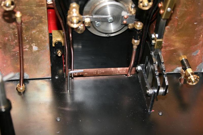
a bit of fiddling around, I managed to get a large, coarse round file
onto the edge of the footplate behind the boiler to make a half
round cut out to allow the pipe through. This picture shows how
both these pipes pass through the footplate.
After
a bit of fiddling around, I managed to get a large, coarse round file
onto the edge of the footplate behind the boiler to make a half
round cut out to allow the pipe through. This picture shows how
both these pipes pass through the footplate. Footnote: I've talked to Andy about this and it seems there maybe a slight difference in the size of the gap behind the boiler, depending on who makes the boiler. I've added a note to kit 8 to suggest that you trial fit the boiler and smokebox to check the size of the gap before bolting everything down. You may or may not have to make the cut-out, but do check.
And so onto the injector itself. After getting it round the wrong way at first (well you've all been there haven't you?) I worked out where the pipe runs were meant to go. The water feed is obvious when you have the tank in place, it's a 'U' shape dropping down through the footplate.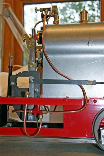 The
steam feed was not so obvious at first but goes forward, through a
cutout in the running board behind the tank and then up to the steam
valve on the turret. The boiler feed from the injector swings
round behind the reverser quadrant and up to the boiler clack through
the newly created cut out in the footplate. These pictures show it more clearly and you can see the connection with the boiler clack in the picture above.
The
steam feed was not so obvious at first but goes forward, through a
cutout in the running board behind the tank and then up to the steam
valve on the turret. The boiler feed from the injector swings
round behind the reverser quadrant and up to the boiler clack through
the newly created cut out in the footplate. These pictures show it more clearly and you can see the connection with the boiler clack in the picture above.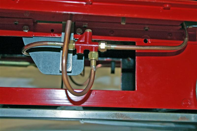
October 20th
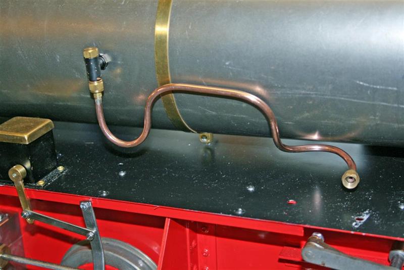
After refitting the boiler clacks I could then complete the bending for the left hand pipe work which connects the hand pump in the side tank to the boiler. This took many attempts before I was satisfied. This picture shows the tortuous shape of this pipe.
Fitting the handpump and pipework is next and this turned into quite a challenge. There's not a lot of room inside the tanks and into the left hand one has to go the hand pump and its pipe connections to the boiler, the axle pump bypass valve and its internal delivery pipe and fittings, plus the fitting to supply the axle pump itself. If you've got very large hands then it's probably time to seek out someone with smaller ones!
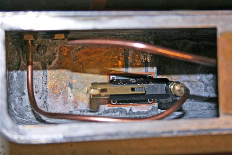
After some grazed knuckles and a few choice words, I did manage to get everything into place. It's not easy to take a photo of the inside of a tank but this will give you an idea. The long pipe coming in from the right at the top is the axle pump bypass delivery pipe. It's there to prevent water being pumped out the top of the tank, apparently.
Remaining jobs were to fix the tanks in place on the running boards and couple up all the pipework. That also took quite a while as some of the fittings are in quite an awkward position. I admit that I'm beginning to wonder if I've done the right thing in not working on the tanks to clean them up first. I think I'm going to have to undo much of this work in order to prepare them for painting. That's another downside of being an impatient person who is keen to see the engine in steam! Oh well, too late to stop now!
Looks like it will be a week or so before I can find time to meet up with Paul (my expert friend from earlier) when we will try to raise steam for the first time. In the meantime I've added a bit more to the kit 10 page.
November 4th
Successful first steam but with a few mistakes are described here First Steam
Back to kit 8 Home On to kit 10